Modelling a parametric ducted propeller based on 19A NACA-profile.
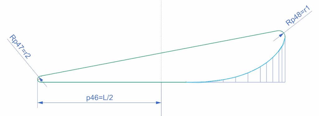
Establishing master sketch for NACA profile
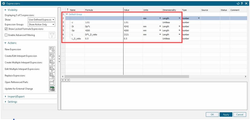
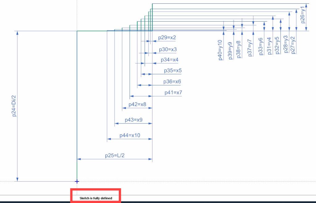
- Establish main input parameters in expressions
- Construct origin for NACA profile
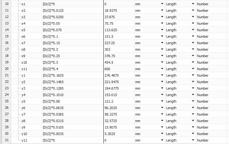
- Create expressions for profile coordinates
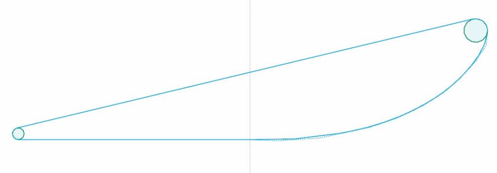
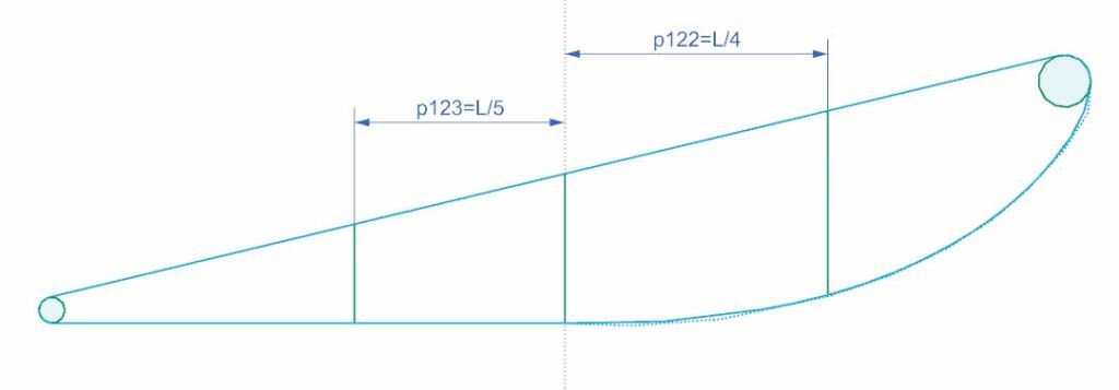
- Create points for inlet profile and add dimensions
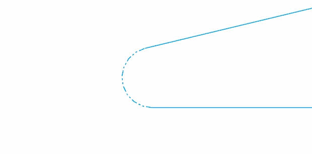
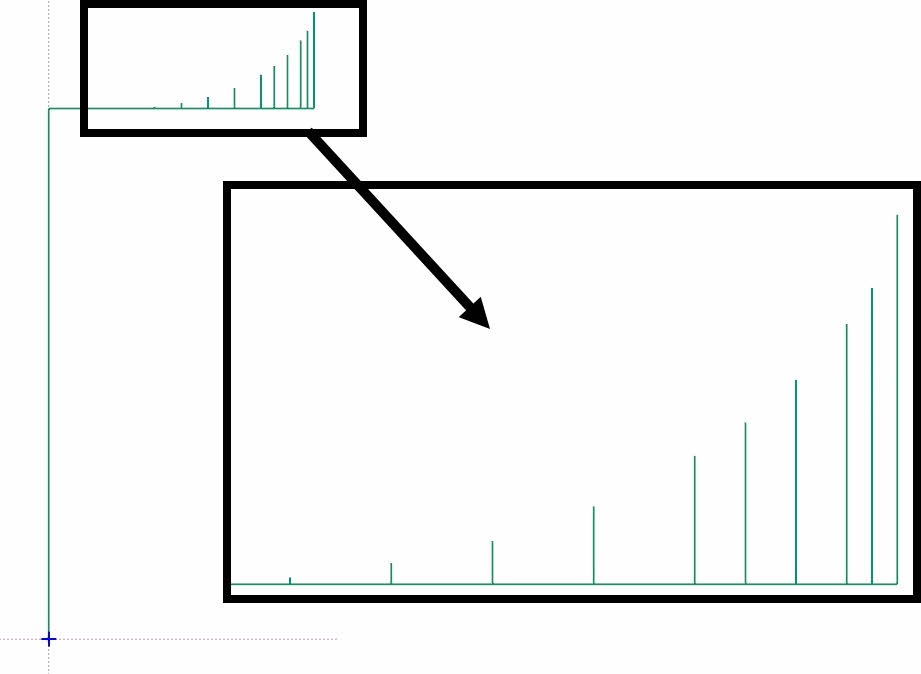
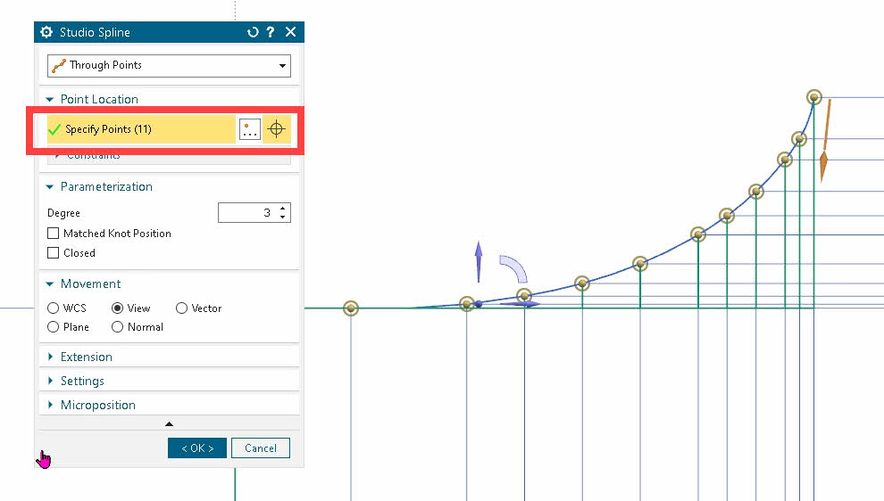
- Create spline on points
- Test sketch robustness and scalability by changing propeller diameter (Dp)

Creating sketch for nozzle cross section
- Create a new sketch and project the spline curve into the new sketch
- Construct the remaining sketch geometry. Make sure its a closed profile

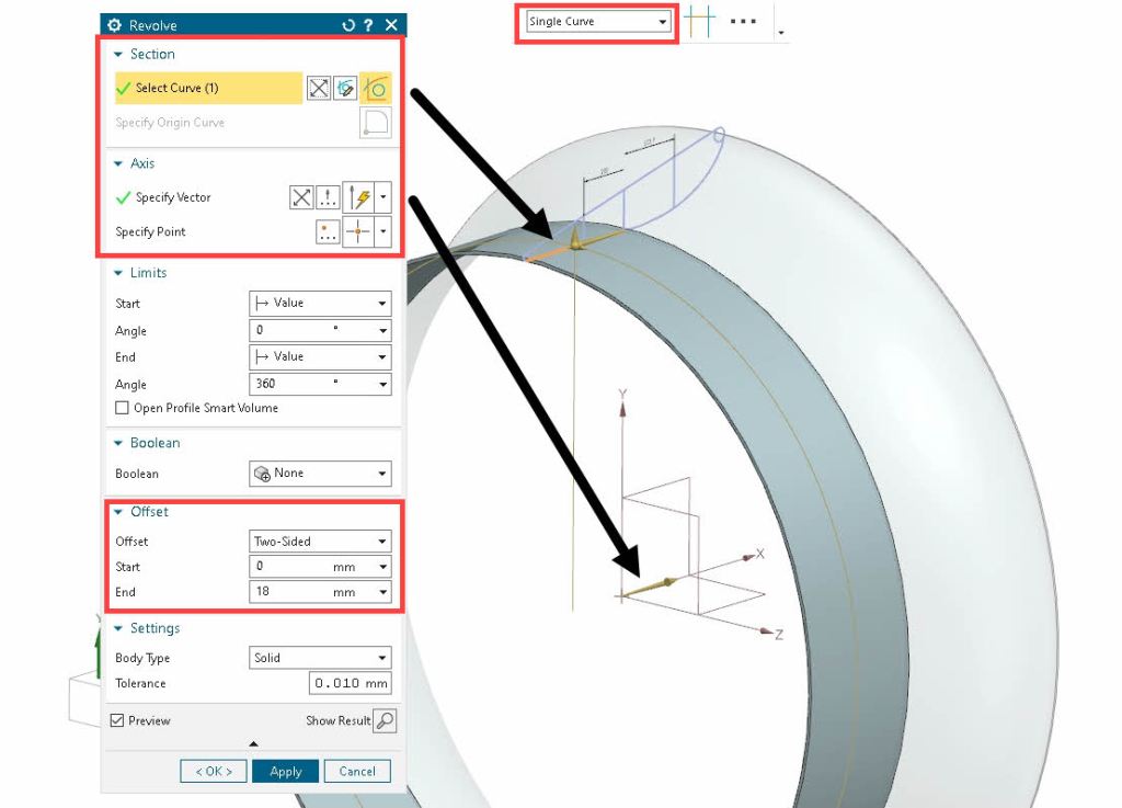
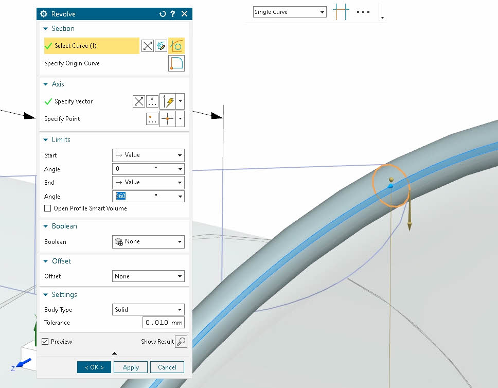
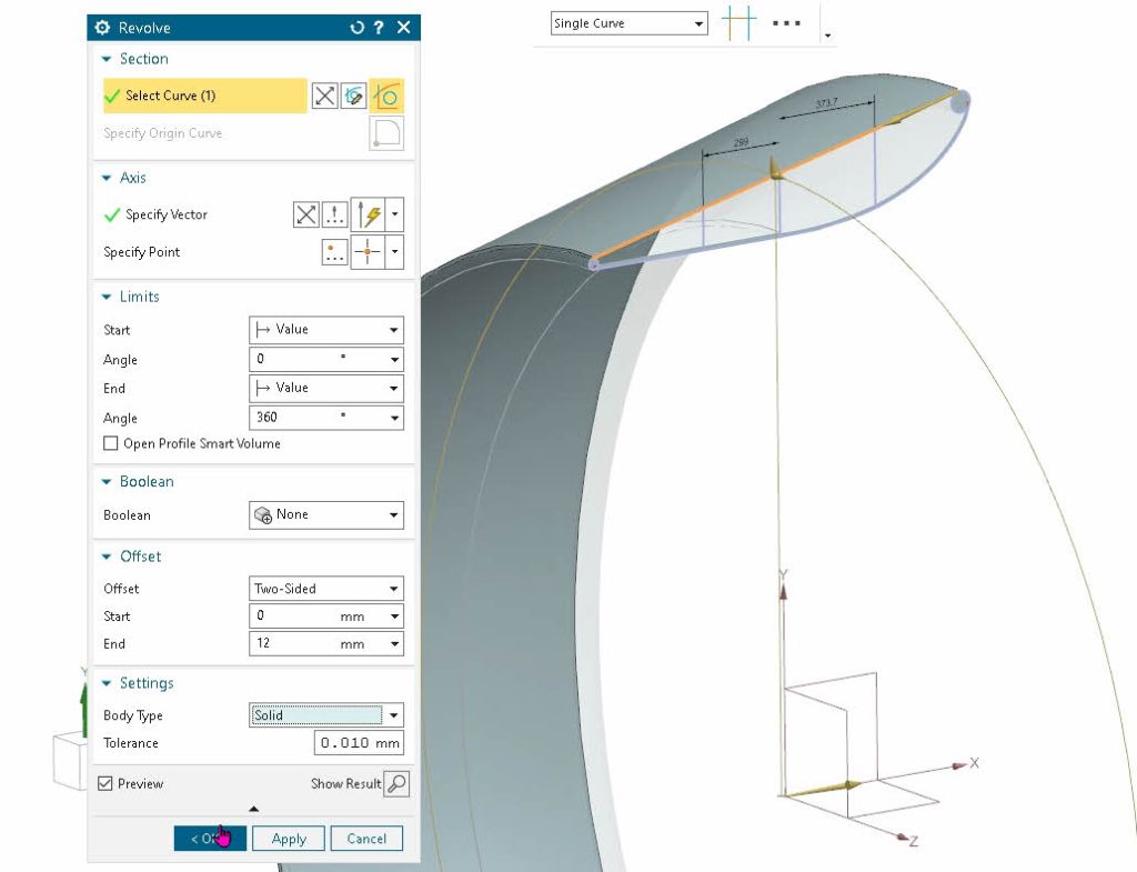
Creating 3D-geometry – Wet surfaces
Designing detail structure
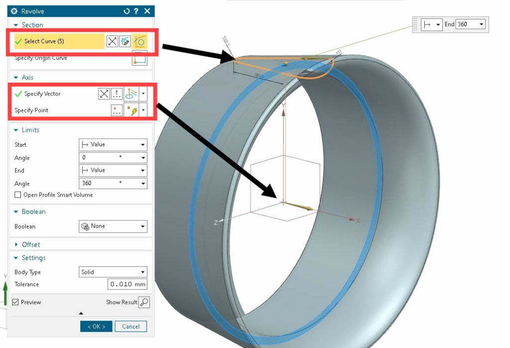
- Create new sketch in XY-plane
- Link curves from master sketch into the sketch
- Convert R1 and R2 curves to reference geometry.
- Draw circles for R1 and R2 constrained to center point and diameter.
- Create lines for internal rings and add dimensions.
- Exit sketch and test sketch scalability again by changing propeller diameter, DP
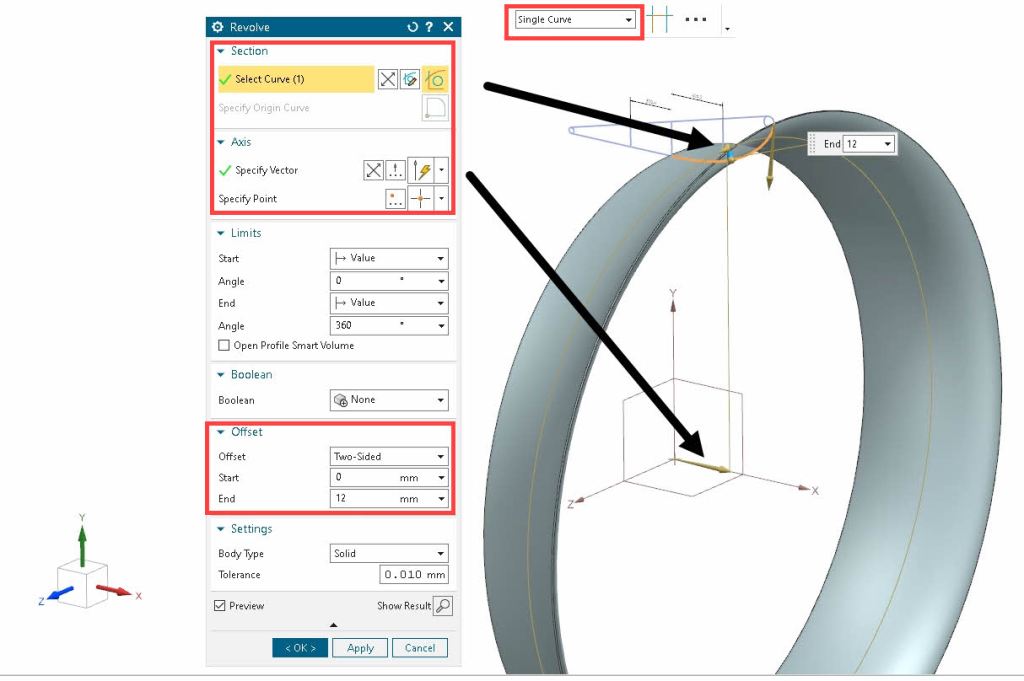
- Use revolve to create plate geometry by selecting single curve and offset to add thickness.