When designing new products a library of mechanical components will have a great impact on the design process and speed. Most mechanical components can be downloaded from web, but it is still still useful to know how to model parts defined by a ISO standard. Especially when creating table driven part families and smart libraries. This blog post describes the modelling concepts for simple shafts, bolted connections and a roller bearing.
Solid shaft
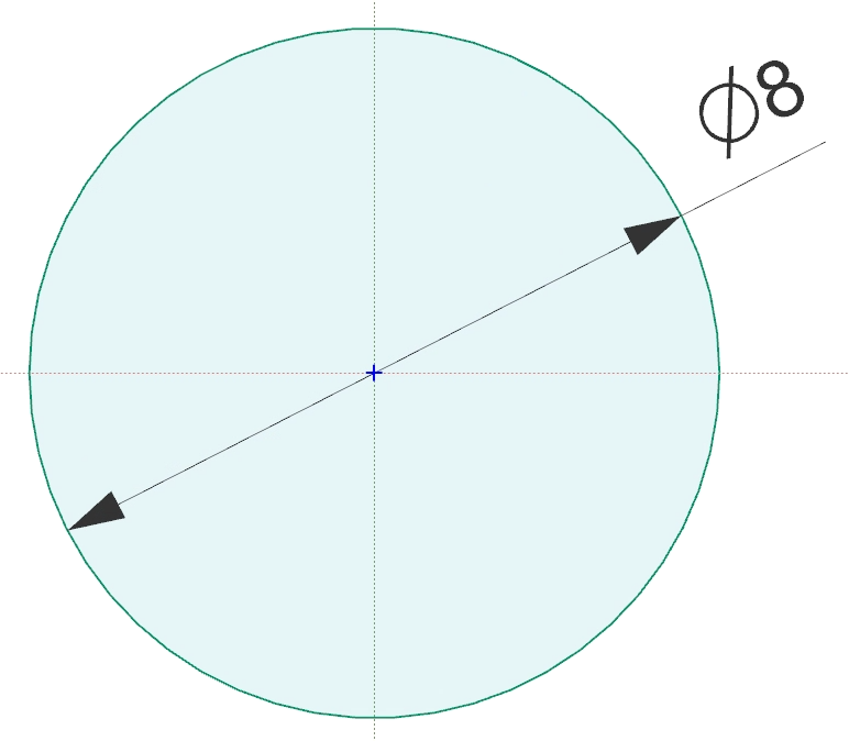
Stainless steel linear rail guides are used in many 3D-Printer builds and kits. One of the most common one is a stainless shaft with diameter Ø8mm and length L=250mm. One simple way to model this part is to create a sketch in the XY-Plane and Extrude the sketch along the Z-axis. As shown in picture and video below.


Hollow shaft
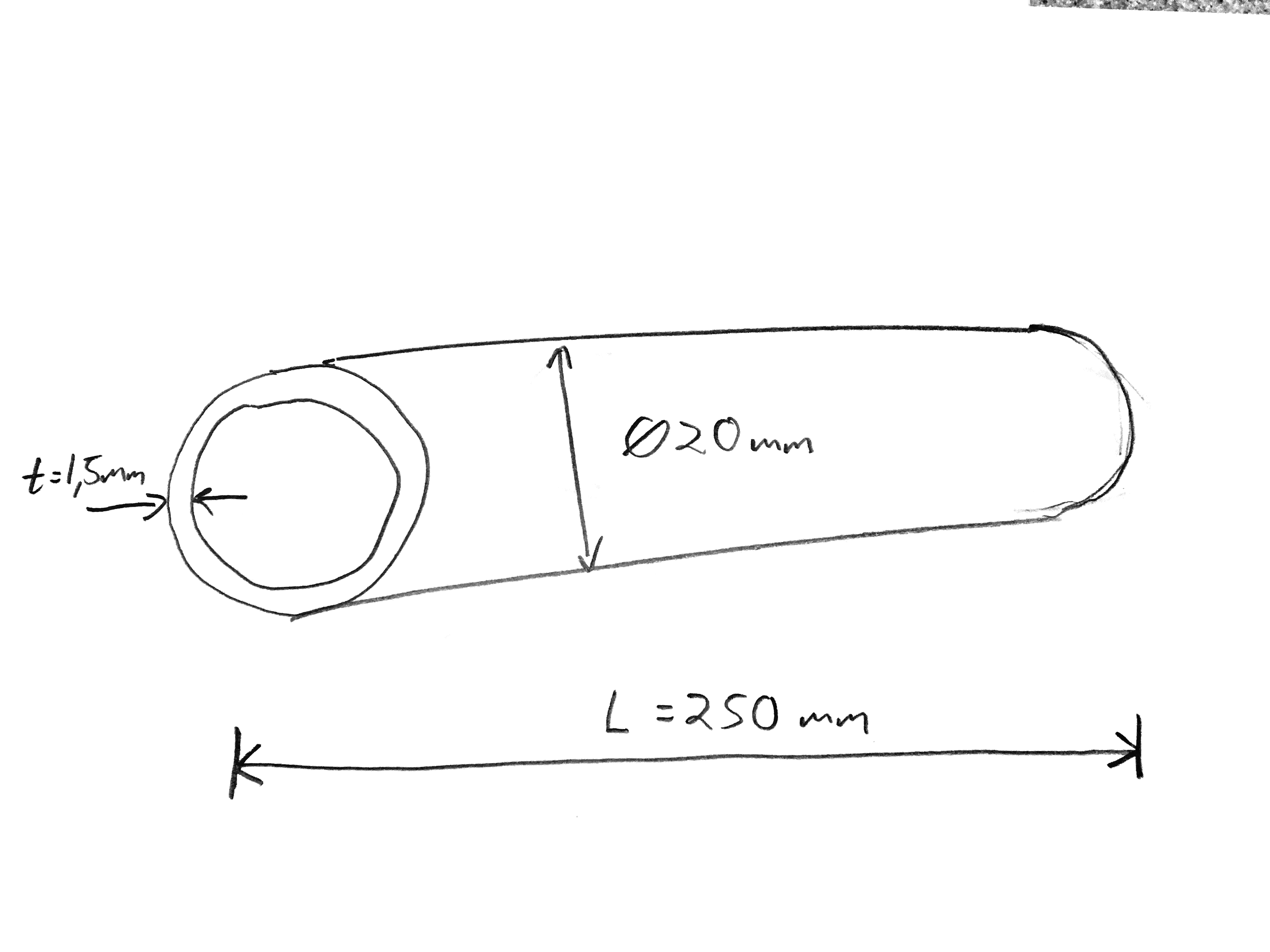
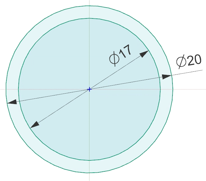
This video shows how to model a hollow shaft with outer diameter d_outer=20mm, wall thickness t=1,5mm and length L=250mm.

Plain washer – ISO 7089
Hex nut – ISO 4032
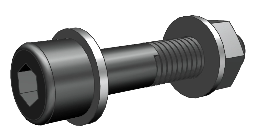
Hex head bolt – ISO 4014
Socket head bolt – ISO 4762
Roller bearing – 608 Deep groove ball bearing
This video shows how to model a 608 Roller bearing based on dimensions from the SKF catalogue.

